
Sep 10, 2025
Events
SEMICON Taiwan 2025
Meet us from Sept 10-12 in Taipei at Nangang Exhibition Center, TaiNEX1, hall 1 4F, booth number M0942.
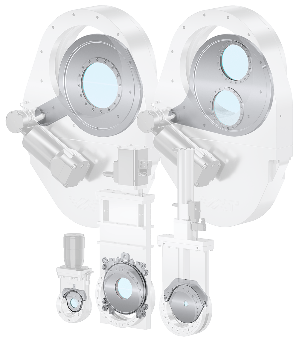
| Window, orifice or filter foil inserts option are offered for the following vacuum valve series: 01.0 Mini UHV Gate Valve |
| 10.8 UHV Gate Valve |
| 15.0 FV/ 15.1 HV/ 15.2 UHV Isolation Gate Valve |
| 16.2 HV Pendulum Isolation Valve |
The MONOVAT sealing technology used in the 01.0 Mini UHV Gate Valve allows a window, orifice or filter foil to be mounted into the vacuum valve gate. These can be integrated by simply opening the valve housing without removing the valve from the system. The window, orifice or filter foil is sandwiched between the O-ring and a screwable retainer ring. A special mounting tool, supplied with each valve when the option is ordered, allows easy replacement.

The window insert is placed in the valve gate. The window gals is sandwiched between an O-ring and a screwable retainer ring to easy change it, if needed.


| a | Section A-A | f | Window glass |
| b | Valve gate | g | Screwed retainer ring |
| c | Elastomer seal for window Ø21.95 x 1.78 | h | Thickness of gate 4 mm |
| d | Diameter of glass Ø24 ±0.2 | i | Thickness of glass 1.5 ±0.1 |
| e | Optically free diameter Ø21 ±0.2 | j | Holes for assembly tool |
| Window specification | Optically free diameter: 21.0±0.2 Outer diameter: 24.0±0.2 Glass thickness: 1.5±0.1 Standard window glass material: Borosilicate or sapphire (Other materials have to be supplied by the customer) |
| Options | Blanking plate in gate (instead of a window glass) 2 valves welded together 3 valves welded together |
| Spare parts | Elastomer seal Retainer ring to hold window glass in place. Assembly tool Borosilicate window glass Sapphire window glass Blanking plate |
| Leak testing | Each valve is leak tested with the window glass installed. |
The orifice in the gate enables a controlled flow. This option is usually only used for two valves welded together.
Standard Orifice in Gate (0.05 to 15 mm)
The orifice is sandwiched in the same way as a windows glass between an O-ring and a screwable retainer ring. It enables a controlled flow and is usually combined with another valve to provide the isolation function. Both valves are in such a configuration welded together to avoid additional sealing requirements.


| a | Section A-A | e | Diameter of orifice 24.0±0.2 | |
| b | Valve gate | f | Thickness of gate 4 mm | |
| c | Elastomer seal for orifice Ø21.95 x 1.78 | g | Thickness of orifice | |
| d | Screwed retainer ring Ø24 ±0.2 | h | Holes for assembly tool |
| Orifice specification | Sizes: 0.05 to 15 mm Outer diameter: 24.0±0.2 Thickness: 1.5±0.1 Standard material: AISI 301 |
| Options | Opening in gate to install a standard orifice (orifice not included) Blanking plate in gate (instead of an orifice) 2 or 3 valves welded together |
| Spare parts | Elastomer seal Retainer ring for standard orifice Assembly tool Blanking plate orifice: 0.05 to 15 mm |
| Leak testing | Each valve is leak tested with a blanking plate installed to ensure leak tightness at the seat. After leak testing, the blanking plate is removed and the customer-specific orifice installed. |
Small Orifice in Gate (0.01 to 0.1 mm)
The orifice is sandwiched between a M4 holding screw and the gate. There is no seal between the orifice and the gate. This means that the valve is not leak tight at the seat when a blanking plate is used instead of an orifice. The orifice can be replaced with a screwdriver size 3.


| a | Section A-A |
| b | Valve gate |
| c | Thickness of gate 4 mm |
| d | Diameter of orifice 3.00/-0.05mm |
| e | Holding screw M4 |
| Orifice specification | Sizes: 0.01 to 0.1 mm Outer diameter: 3.00/-0.05mm Thickness: 0.3 mm Standard material: AISI 304 |
| Options | Opening in gate to install a small orifice (orifice not included) Blanking plate in gate (instead of an orifice) 2 or 3 valves welded together |
| Spare parts | Elastomer seal Retainer ring for small orifice Holding screw M4 Orifice 0.01 to 0.1 mm Blanking plate |
| Leak testing | Leak testing is provided in the standard valve configuration without orifice or in the configuration of two valve welded together one providing the isolation function and the other the orifice feature. |
Standard Filter Foils in Gate
The valve is supplied without the filter foil. This must be procured and installed separately.


| a | Section A-A | f | Space for foil 0.2...0.4 mm |
| b | Valve gate | g | Retainer ring for foil filter |
| c | Elastomer seal for foil Ø21.95 x 1.78 | h | Thickness of gate 4 mm |
| d | Diameter of foil Ø25 ±0.2 | i | Thickness of foil 0.2 – 0.4 mm±0.1 |
| e | Free diameter Ø21 ±0.2 | j | Holes for assembly tool |
| Foil filter | Free diameter: 21.0±0.2mm Outer diameter: 25.0±0.2mm Thickness: 0.2 - 0.4 mm |
| Options | Opening in gate to install a foil filter (foil filter not included) 2 or 3 valves welded together |
| Spare parts | Elastomer seal Retainer ring for foil filter Assembly tool |
| Leak testing | Each valve is leak tested with a blanking plate and a window retainer ring. The retainer ring for foil filter is only installed after the leak test procedure. |
LUXEL (VF111) Filter Foil in Gate
The LUXEL (VF111) filter foil line brings several advantages to soft X-ray applications. The filters are threaded into the gate valve and are designed to reject visible light, to remove soft scattered radiation, and to limit the X-ray/EUV bandpass to the area of interest. The valve is always supplied without the LUXEL filter. The valve or retainer ring has to be send to LUXEL company to have the filter installed. The retainer ring with the LUXEL filter can be replaced without the need to change the bonnet seal or removing the valve from the system. Compared to design option with window, the only difference is the retainer ring. The gate, the O-ring and the assembly tool do not differ.


| a | Section A-A | f | LUXEL filter |
| b | Valve gate | g | Retainer ring for LUXEL filter |
| c | Elastomer seal for foil Ø21.95 x 1.78 | h | Thickness of gate 4 mm |
| d | Diameter of foil Ø20.6 ±0.1 ±0.05 | i | Thickness of LUXEL filter 1.74 0-0.1 |
| e | Free diameter Ø15.9 ±0.2 | j | Holes for assembly tool |
| Foil filter specification | For detailed information please consult the LUXEL website |
| Options | Opening in gate to install a LUXEL filter (filter not included) 2 or 3 valves welded together |
| Spare parts | Elastomer seal Retainer ring for LUXEL filter Assembly tool |
| Leak testing | Each valve is leak tested with ablanking plate and a window retainerring. The retainer ring for LUXEL filter is only installed after theleak test procedure. |
The 10.8 UHV Gate Valve uses the VATLOCK sealing technology. To integrate the window in the gate the sealing mechanism is slightly altered to avoid the leaf spring obstructing the optically free passage of the window.


| DN 63 | DN 100 | |
| Ø a | 70 | 100 |
| Ø b | 46±0.2 | 50±0.2 |
| Ø c | 40 | 43 |
| Ø d | M48x1.5 | M52x1.5 |
| e | 21 | 21 |
| f | 4±0.1 | 4±0.1 |
| g | 3.3 | 3.3 |
| h | 9 | 9 |

| DN 160 | DN 200 | |
| Ø a | 150 | 200 |
| Ø b | 75±0.2 | 97±0.2 |
| Ø c | 68 | 90 |
| Ø d | 90 | 113 |
| e | 21 | 26.5 |
| f | 6±0.1 | 6±0.1 |
| g | 3.7 | 3.7 |
| h | 8 | 12 |
| Window specification | The maximum size of the window is defined by the VATLOCK mechanism. In this regard, the valves DN 250 and DN 320 do not allow a window. Standard window material: Borosilicate or sapphire(other materials have to be suppliedby the customer) Optically free diameter C valve DN 63: 40 mm valve DN 100: 43 mm valve DN 160: 68 mm valve DN 200: 90 mm Glass thickness valve DN 63 – 100: 4 mm valve DN 160 – 250: 6 mm Mounting position of valve: Any |
| Spare parts | Assembly tool for window exchange DN 63 Assembly tool for window exchange DN 100 |
| Leak testing | Each valve is leak tested with a blanking plate and a window retainer ring. |
The series 15 UHV isolation vacuum gate valves uses the MONOVAT sealing technology, similar to the 01.0 Mini UHV Gate Valve. In this regard the same technical specification apply. Please refer therefore to the 01.0 Mini UHV Gate Valve section. The maximum size of a window, orifice or foil is generally defined by the diameter of the gate.


| a | MONOVAT gate |
| b | Retainer ring |
| c | Window |
| d | O-ring |
| Window specifications See series 01.0 |
With window With Orifice With foil filter |
The series 16.2 uses a pendulum valve design that allows to mount large windows. E.g., a DN 250 valve can have a window with an optical free diameter of 200 mm. Also having more than one window in the gate is an option. The window is sealed by O-rings that also prevent glass-metal contact during thermal expansion.


| a | Gate |
| b | Screw |
| c | Flange |
| d | Window |
| e, f | Seals |
 |
Valve seat side |
| Window specifications | ||||
| Valve size DN | Window material | Optically free diameter "A"1 mm |
Thickness of glass mm |
|
| 200 | Borosilicate Sapphire |
130 170 |
6 5 |
|
| 250 | Borosilicate Sapphire |
130 200 |
6 6 |
|
| 320 | Borosilicate Sapphire |
150 250 |
8 6 |
|
| 350 | Borosilicate Sapphire |
150 250 |
8 6 |
|
| 400 | Borosilicate Sapphire |
150 250 |
8 6 |
|
| 500 | Borosilicate Sapphire |
on request on request |
1 Above specification includes the largest possible windows. Smaller windows on request. Due to the weight of the window, it is not possible to mount the valve in any position.


