SEMICON Taiwan 2025
Meet us from Sept 10-12 in Taipei at Nangang Exhibition Center, TaiNEX1, hall 1 4F, booth number M0942.
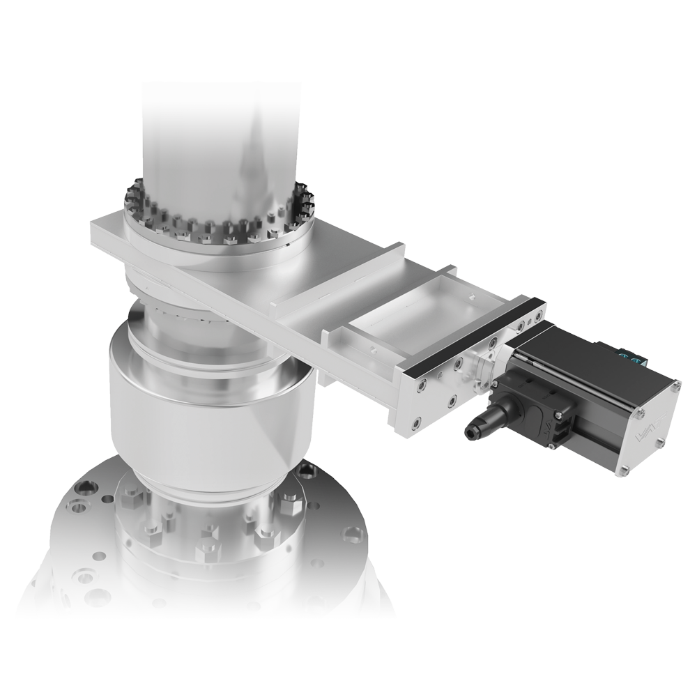
The 11.1 HV Gate Valve series is equipped with VATLOCK technology which is specially developed to provide reliable sealing without any friction at the gate seal. The VATLOCK mechanism also prevents valve failures thanks to the mechanical lock-in at the closed end position.
Already installed in thousands of demanding applications under various process conditions, the 11.1 series and its predecessor the 11.0 have proven their outstanding reliability. They have become the standard for any HV isolation requirement in sizes from DN 63-320 mm (2.5” - 11.5”).
With its robust design the 11.1 series meets all of the requirements for a reliable functioning HV gate valve. Designed to reliably perform for an especially high number of process cycles, the 11.1 sets the standard for general purpose HV gate valves.
The series provides various actuation and flange connection design options so it’s easily integrated into any HV system. A wide range of special options such as windows and ports ensure optimal fit to the application.


The 11.1 HV Gate Valve is available in manual, pneumatic and 3-position pneumatic versions. The valve can be controlled by a solenoid valve either “on board” or in a distant location if required. The solenoid valve’s standard voltage is 24V DC but other voltages are available upon request. The valve position is indicated with a double position indicator - two switches each for the “Open” and “Closed” positions - with change-over contact.
The standard options for flange connectors are ISO-F, CF-F, ASA-L and JIS. Customer specific flanges with and without water-cooling can be integrated.
The gate sealing can be either an O-ring seal or a vulcanized seal up to DN 200 mm (8”). The vulcanized seal is the recommended solution because of its superior performance in terms of vacuum property and reliability.
Features:
Benefits:
| Sizes | DN 63 (2½’’), DN 80 (3"), DN 100 (4"), DN 160 (6"), DN 200 (8"), DN 250 (10"), DN 320 (12") | ||
|---|---|---|---|
| Actuator | 3-Position-Pneumatic | Double acting | |
| Manual | With Crank Handle | ||
| Body Material | Stainless Steel | ||
| Feedthrough | Bellows | ||
| Standard Flanges | ISO-F, CF-F, ASA-LP, JIS | ||
| Leak Rate | Valve Body | < 1 × 10⁻⁹ mbar ls-1 | |
| Valve Seat | < 1 × 10⁻⁹ mbar ls-1 | ||
| Pressure Range | 1 × 10⁻⁸ mbar to 1.6 bar (abs) (DN 63 – 200) 1 × 10⁻⁸ mbar to 1.2 bar (abs) (DN 250 – 320) | ||
| Differential Pressure | On the Gate | ≤ 1.6 bar (DN 63 – 200) ≤ 1.2 bar (DN 250 – 320) | |
| At Opening | ≤ 30 mbar | ||
| Cycles until first Service | 200 000 | ||
| Temperature | Valve Body | ≤ 150 °C | |
| Actuator | ≤ 80 °C | ||
| Solenoid Valve | ≤ 50 °C | ||
| Position Indicator | ≤ 50 °C | ||
| Heating and Cooling Rate | ≤ 50 °C h-1 | ||
| Material | Valve Body | AISI 304 (1.4301) | |
| Mechanism | AISI 316L (1.4404) (DN 63 – 200) AISI 304 (1.4301) (DN 250 – 320) | ||
| Bellows | AISI 633 (AM350) | ||
| Seal | Bonnet, Gate | FKM (Viton®) | |
| Mounting Position | Any | ||
| Solenoid Valve | 24 VDC, 5.4 W (others on request) | ||
| Position Indicator: Contact Rating | Voltage | ≤ 50 VAC/DC | |
| Current | ≤ 1.2 A | ||
| Valve Position Indication | Visual (Mechanical) | ||